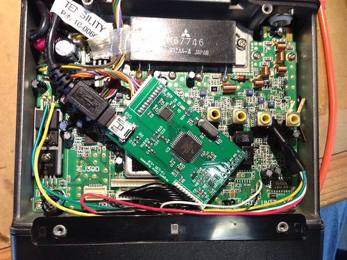
I recently acquired an Alinco DR-135 radio with an integrated EJ-41U TNC unit.
I decided to replace the TNC with an Argent Data Tracker3 T3-135 module. After installing the module, however, the TNC board would not power up.
I measured the 5V line feeding the TNC module at around 3.5V. When I replaced the module with the original EJ-41U, I measured around 3.8V (although that unit seemed to work OK, even on such a low voltage).
Update: If anyone is doing this mod, don’t pull power from the 7808 like I did. See below..
I read through the schematic and found out that the power for the TNC was running through a transistor (Q130, of type DTA114YU), which was effectively working as a NOT gate, inverting the signal from the CPU. It seems like the transistor could not source enough current to run the TNC (about 50mA)
It seems that the later models of the radio (Mk2 and Mk3) have a separate 5V regulator for the TNC, that is only enabled when the output of Q130 is HIGH.
I then purchased a power regulator from SparkFun that had an enable line. It’s rated at 150mA so it should handle the TNC without issue.
I didn’t have any kind of breakout board that would work with a SOT-23-5 part, so I took a bare copper PCB and cut out lines between where the leads are.
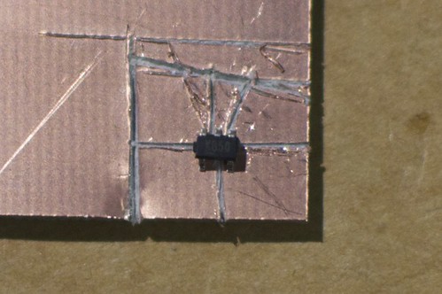
I then soldered it on and attached wires to the input and output, along with a 1µF capacitor
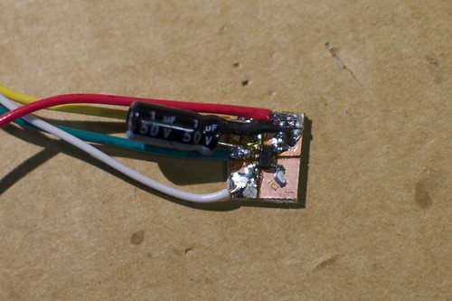
Red: 12V input
Yellow: 5V output
Green: Ground
White: Enable
The reference bypass (pin 4) is not needed.
The whole unit was then heat shrinked.

I then attached the input lines to the 12V and GND on the input of the 7808 regulator (IC115 on the schematic), attached the ENABLE line to the output of Q130 (the original TNC module 5V line), and attached the 5V output from the regulator to the 5V input of the T3-135.
So far it seems to work OK, although I have not had time to actually take it on the air yet.
Update 2013-09-06:
I turned on the radio one day and the display started blinking. After resetting a few times, and looking online, I tracked it down to no voltage on the input of the 7808. Turns out it runs through a transistor (Q122 on the board) on the board, which had blown out.
I simply removed Q122 and solder bridged pins 2 and 3, and the radio works again. If you are doing this mod, attach the 12v line to the regulator somewhere else than the 7808.
Possibly related to that, it seems like the heat shrink on the capacitor is not enough to insulate the Vin from the Vout on the regulator board. You’ll want to rearrange things to keep from blowing the T3-135 like I did. Turns out that 13.8v doesn’t work so great on a processor expecting 5v.
Hi – my DR-135 just started doing the “blinking LCD” that you described at the end, but I have not done any modifications and use an external TNC. Do you happen to have any links to info about what causes that? Should I just look into Q122 also? Thanks for any info you might have, I know this is a 3 year old post!
I’d probably check the input and output voltages on the 7808 regulator first, as that may be a likely culprit
You should be able to find the service manual online for further troubleshooting (try searching for “Alinco_DR135 VHF Tranciever_Service Manual.pdf” or “alinco-dr-135-235-435-sm-copyr2000.pdf”).
Thanks for this. I was getting the blinking display with no audio. I checked and was only getting 1.6v to the 7808 regulator. Dropped some solder on the collector to emmiter of Q122 and the audio came back and display stopped blinking. I found a generic power pnp from a scrap board and used that to replace Q122. It’s working! BTW mine is a DR-130 . Denton KE8BG